Nomenclature
- SEUP - Simple Electric Utility Platform. This is an end-to-end microgrid management solution designed and developed at WEMPEC, UW-Madison. It has various components listed below.
- HEM - Homegrid Energy Manager. Each home, building etc. becomes an autonomous entity called a homegrid which is managed by a HEM.
- MGO - Microgrid Operator. All the HEMs of a microgrid are managed by the microgrid operator.
- MEM - Microgrid Energy Manager - The entire infrastructure system to host multiple MGOs together is termed as microgrid energy manager
- HEMCore - hardware module used for communication and computing in a homegrid.
- HEMAC/DC - hardware modules used as power interface for power system.
- HEMApp - core software running HEM
- MEMCloud - cloud platform for microgrid management
- MEMWeb - web application for microgrid monitoring, control and management.
Introduction to SEUP
The physical system at it’s most basic level is composed of two boards: the HEMCore board and the HEMAC/DC Board. These boards have an array of functionalities used by the microgrid to maximize performance for the user. The HemCore board, along with a processor mounted on it, is the brains of the device. It controls and maintains all of the services the microgrid has to offer. The HEMAC/DC board controls the microgrid’s power distribution to the various loads that are connected via nodes. Alongside the physical components of the system, there are several digital features that enable more robust control and monitoring of the system. These features include a cloud platform (MEMCloud) and web application (MEMWeb) that allows users to control their grid with ease and monitor their energy usage over time. Users simply need a stable Internet connection. The system also includes text-based control and monitoring (MEMText) of the grid through a variety of sms commands which are detailed later on.
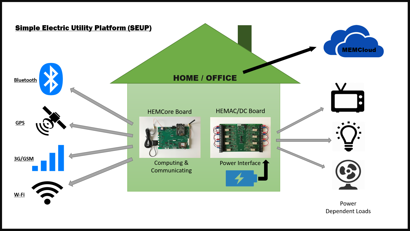
The system comes with a variety of communication features including: cellular, Wireless/Wired and Bluetooth. This not only allows for more flexibility in how one can control their grid but it also provides the user with a backup in case one feature cannot be accessed at a given time. The grid uses the cloud for encrypted data transmission/reception meaning your information is protected. GPS functionality allows users to geolocate their grid to get accurate scheduling time
Where can SEUP be used?
- Microgrids/Smartgrids
- Home Automation
- Building Energy Management
- Campus Grid Management
- Industry Power Management
- Teaching/Research
SEUP System Overview
HEMCore Board Overview
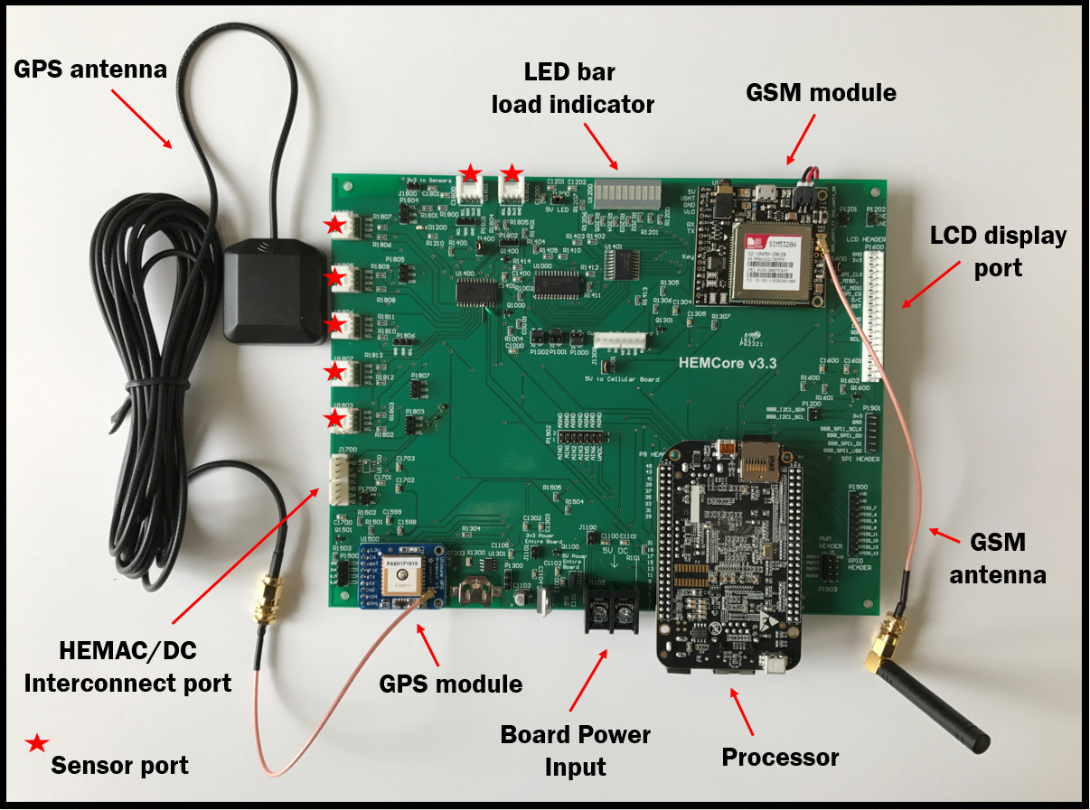
The HEMCore board is the hub for all microgrid processes and communications made to the user/cloud. It has a processor mounted onboard that controls these processes which can be connected to the internet wirelessly via a USB wireless adapter or through Ethernet. The processor also controls the functionality on the microgrid’s maintenance LCD screen. The board uses a GPS module to obtain the microgrids location and acquire the local time. The LED bar indicates the status (on/off) of each load connected to the board. The attached GSM module allows the device to send and receive texts. The board is powered by a 5V source via the 2 screw terminal block. On top of everything else, the processor has a microSD card slot which allows power usage data to be stored locally on an SD card in case the connection to the cloud is interrupted
HEMCore AC/DC Board Overview
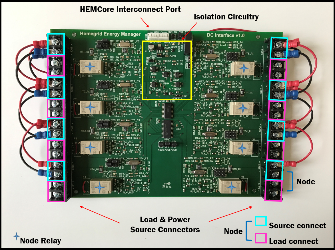
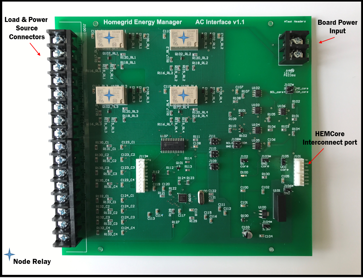
The HEMAC and HEMDC boards are used for power facilitation between the HEMCore Board and the various loads connected to the microgrid system. These boards can open up/shut off power to these loads and also give feedback to the processor on power consumption and other useful data. Loads such as lights and fans are connected to boards through the terminal blocks marked with the text “LD X”. Each load section has text indicating how to properly hook up the loads. The “+” and “-” symbols designate where to screw in the phase (power) and earth (ground) wires respectively. The DC and AC boards incorporate isolation circuitry to reduce the risk of failure and increase the safety of people working on the device
Note: The term “Node” will be used throughout to describe aspects of the device. for all intensive purposes, a node is what a load (fan, light, etc.) is hooked up to on the board. The node channel can either be opened (powered) or closed (un-powered). The channel is controlled by the Node relays connected to each node. There are 8 nodes on the DC board and 6 nodes on the AC board (pending). When sending commands via sms, we use node NOT load